Visitors can check out the Forum FAQ by clicking this link. You have to register before you can post: click the REGISTER link above to proceed. To start viewing messages, select the forum that you want to visit from the selection below. View our Forum Privacy Policy.
Want to receive the latest contracting news and advice straight to your inbox? Sign up to the ContractorUK newsletter here. Every sign up will also be entered into a draw to WIN £100 Amazon vouchers!
It's the closest I could find in Google images. Just pretend that the AND gates are NAND gates and that the wires cross. Are you imagining a naughty multivibator now, or a monoflop?
Can you remember this stuff? I've forgotten what little I knew and never used.
Can sort of remember it, but I think the edge triggering turns it in to a bi-stable jobby (use an R-S flip flop?). No doubt Zeity will be along to smite us at some point
+50 Xeno Geek Points Come back Toolpusher, scotspine, Voodooflux. Pogle
As for the rest of you - DILLIGAF
Purveyor of fine quality smut since 2005
CUK Olympic University Challenge Champions 2010/2012
Can sort of remember it, but I think the edge triggering turns it in to a bi-stable jobby (use an R-S flip flop?). No doubt Zeity will be along to smite us at some point
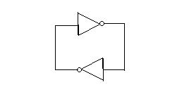
Here's a simpler one:
But here you have to imagine an extra inverter (not gate) in the circuit [due to inadeques in my searches in Google images again]. Bzzzzz. Not as sexy.
For each inverter - take one two-input NAND gate and feed the same into each input, take the output and feed into the inputs of the next NAND gate etc. etc. Or have I missed the point?
'Kin 'ell. It's a slow night tonight.
+50 Xeno Geek Points Come back Toolpusher, scotspine, Voodooflux. Pogle
As for the rest of you - DILLIGAF
Purveyor of fine quality smut since 2005
CUK Olympic University Challenge Champions 2010/2012
For each inverter - take one two-input NAND gate and feed the same into each input, take the output and feed into the inputs of the next NAND gate etc. etc.


Comment